Industry news
NACS Charge Inlet: AC and DC Compatibility Explained
How Does NACS Use the Same Pins for AC & DC Charging?
The electric vehicle (EV) landscape is rapidly evolving, with charging infrastructure playing a crucial role in its growth. While various charging standards exist, harmonization remains a key challenge. The North American Charging Standard (NACS), also known as SAE J3400, aims to address this by introducing a single port capable of handling both AC and DC charging. This article delves into the inner working principle of the NACS inlet.
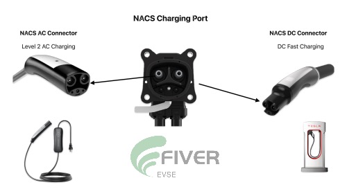
The NACS Charge Inlet Pin Layout: Simplicity Through Design
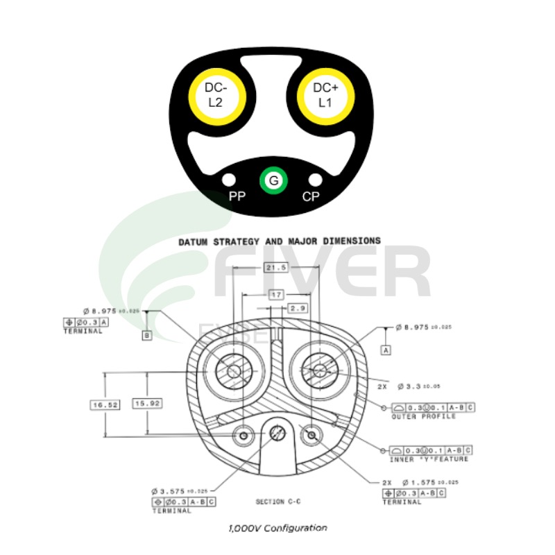
NACS Charge Port Contacts Function Definition:
DC+/L1:
DC Charging: Positive terminal for the DC voltage feed.
AC Charging: Line 1 in split-phase or sole line in single-phase.
DC−/L2:
DC Charging: Negative terminal for the DC voltage feed.
AC Charging: Line 2 in split-phase or neutral in single-phase.
Ground (G): Provides a connection to earth and serves as a reference point for control signals.
Control Pilot (CP): Enables digital communication between the charging system and vehicle using the IEC 618516 standard. Transmits a pulse-width-modulated signal during DC charging.
Proximity Pilot (PP): Detects the status of the vehicle connector using a low-voltage signal. Disables power delivery when the charging plug is unlocked.
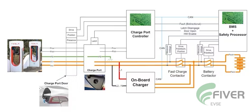
The Secret: Communication Protocols Over shared Pins:
NACS communication protocol: Two Primary Communication Protocols for NACS Charging:
The NACS standard utilizes two primary communication protocols: Basic Signaling (BS) and High Level Communication (HLC).
Basic Signaling (BS):
Uses the same pulse-width-modulation (PWM) scheme transmitted over the CP contact as used in J1772 AC charging systems.
Primarily for safety-related functions and, in the case of AC charging, to advertise the available power level from the charging station.
Can also transmit a 5% pulse width signal to indicate the need for HLC.
High Level Communication (HLC):
A more advanced protocol based on the DIN SPEC 70121 and ISO/IEC 15118 standards.
Transmits modulated high-frequency signals over the CP contact (power-line communication or PLC).
Enables the transmission of digital commands and information for more complex charging scenarios.
In essence, BS provides a basic level of communication for safety and power level indication, while HLC offers a more sophisticated means of data exchange for advanced charging features.
AC or DC - How the System Decides: Electric Vehicle Charging Event Sequence Overview
The charging process for electric vehicles (EVs) involves a series of interconnected steps controlled by both the EV's hardware and software, as well as the charging station's systems. This sequence varies slightly between AC and DC charging, as illustrated in Figures 2 and 3.Key Steps in the Charging Sequence:
Vehicle and Charging Station Connection: The EV is physically connected to the charging station using the appropriate connector (e.g., NACS, CCS).
Communication and Authentication: The EV and charging station establish a communication link and authenticate each other to ensure compatibility and security.
Charging Mode Selection: The charging system determines whether AC or DC charging is appropriate based on the vehicle's capabilities and the available charging infrastructure.
Power Negotiation: The vehicle and charging station negotiate the maximum charging power and voltage.
Charging Initiation: The charging process begins, with power flowing from the charging station to the EV's battery.
Monitoring and Control: The system continuously monitors charging parameters (e.g., voltage, current, temperature) and adjusts the charging rate as needed.
Charging Completion: Once the battery reaches its target state of charge or the charging session is manually terminated, the charging process concludes.
Disconnection: The EV and charging station safely disconnect.
Additional Considerations:
Safety Features: Throughout the charging process, various safety mechanisms are in place to prevent hazards such as overheating, overcurrent, or electrical faults.
Communication Protocols: The specific communication protocols used between the EV and charging station may vary, but they generally involve standardized methods for exchanging information and commands.
NACS DC Charging Sequence Steps Explained
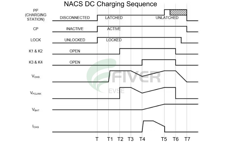
NACS AC Charging Sequence Steps Explained:
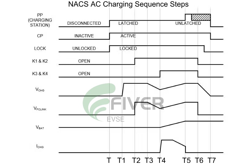
Safety First: How NACS Prevents Dangerous Mix-Ups
Based on above information we can see that, the NACS charge inlet includes interlocks and safety protocols to ensure only one power-delivery path is active at a time to prevent the AC/DC mix-ups and ensure the safety. The NACS connector support vehicle-charger communications using the dual-mode power-line communication (PLC) protocol defined in the IEC 61851 standard. The NACS shared pin charging + safety control system has two modes. The first mode, Basic Signaling (BS), is the same pulse-width-modulation (PWM) scheme transmitted over the CP contact used by J1772 ac charging systems for safety-related functions and to advertise power level for ac charging. The station can transmit a 5% pulse width to indicate the use of High Level Communication (HLC) protocol. The HLC protocol involves transmitting a modulated high-frequency signal over the CP contact (also known as power-line communication or PLC) based on DIN SPEC 70121 and the ISO/IEC 15118 standard and can be used to transmit digital commands and information. This is how the NACS Charge inlet combines AC and DC charging by using these different communication modes and protocols.
F&Q
1> Can NACS inlets support both AC and DC Charging?
Yes! That's its main innovation. The same two power pins carry either AC from a home charger or DC from a fast charger, controlled by the interlock & communication protocols.
2> Is NACS safer than CCS?
Both NACS & CCS are extremely safe when manufactured to standard. NACS achieves safety through sophisticated communication and electronic controls rather than separate physical pins.
3> Why is NACS connector smaller?
By sharing pins for AC/DC and using advanced interlock & communication protocols, NACS eliminates redundant pins needed in the CCS design, resulting in a 40-50% smaller connector.
4>Can I use a NACS charger for any EV?
With the industry shift, most new EVs in North America will have NACS ports by 2025. For current CCS vehicles, adapters will be available.
5> Why Choose FIVER as your NACS charge inlets supplier?
As a specialized manufacturer & supplier of NACS (SAE J3400) Charge Inlets, Fiver provides OEMs, charging networks, and EVSE manufacturers with technically superior, rigorously tested components. We differentiate ourselves through deep expertise in the NACS standard, offering a comprehensive portfolio—from high-current 1000V/350A NACS Charge inlets for ultra-fast charging enabled passenger cars to efficient 600A NACS Charging Port busbar versions for electric commercial vehicles, machineries & next-generation vehicle integration—ensuring the perfect solution for every application. With full customization, direct manufacturer pricing, and comprehensive lifecycle support, our future-proof designs, backed by stringent quality control and reliable supply chains, ensure partners receive not just parts, but a trusted engineering resource for integrating the North American Charging Standard.."
Categories
Latest News
Contact Us
Contact: Jerry Zhan
Phone: WhatsApp: +8618028699987
Tel: +86-023-20791348
Add: No.2201,AESC Center, Yubei District Chongqing China